

There are a few things to note right off the bat about I2C. For one, as mentioned above, it only requires 2 data lines, or wires, regardless of the number of masters and slaves used. This is a big advantage, and in comparison, a SPI (Serial Peripheral Interface) bus needs 4 lines, plus one line for each slave. In this way, I2C scales nicely for large systems and can support up to 1008 slaves if using 10-bit addresses (discussed later). The data rates for I2C devices commonly range between 100 kHz and 400 kHz and, in some cases, as high as 5 MHz.
Alas, useful and cool as it is, I2C is the one that many engineers seem to struggle with the most. While much of this has to do with device addresses and their corresponding documentation, a firm understanding of the protocol can only make things easier, right? That being said and without further ado, let’s get down to business.
Physical Setup
I2C was developed by Philips Semiconductors in the early 1980’s as a means by which multiple integrated circuits could communicate with one another. The design is intended for short distance, synchronous communications, and requires only two active wires regardless of the number of devices that are talking. These lines are SDA (Serial Data Line) and SCL (Serial Clock Line). As you might imagine, data is transmitted across the data line, and the clock establishes the data transfer rate. The current bus master, and only the current bus master, generates the clock signal. A typical setup is shown below.
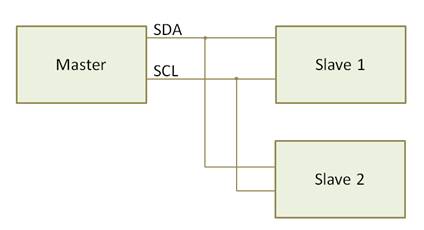
Figure 1: Block diagram for a basic I2C configuration. Two lines are all that are needed to communicate with multiple master or slave nodes – these lines are SDA (Serial Data Line) and SCL (Serial Clock Line).
How it Works
In order for all of these devices to play nicely together, there have to be some rules – or a protocol. Otherwise, the situation would degenerate into a scene reminiscent of Arnold Schwarzenegger’s first day of class in the timeless classic, Kindergarten Cop.

What we are looking for instead is something akin to a skillful school teacher corralling a bunch of kindergartners. Imagine, if you will, a classroom full of children sitting peacefully around their teacher, listening attentively to the day’s lesson (ok, maybe this analogy is a bit of a stretch…). The teacher initiates a dialogue with a student by calling on their name. If the student is paying attention, they respond, and then either listen to what the teacher has to say or answer the teacher’s question.
In a similar fashion, the master device initially sends out a packet over the data line specifying which device they want to talk to. If able, the slave responds, and then the data is sent from the master to the slave or vice versa, as dictated by the master. Finally, the master ends the transmission, which opens the bus up for other masters to communicate. Let’s dig into the nuts and bolts of how this interaction actually takes place.
Communication with a slave is initiated from the master by issuing a specified start condition. When it comes to the start condition, it’s first come, first served. If there’s a case where two masters try to grab the line at the same time, whichever gets their first is the winner. The I2C protocol has established that this start condition is met when the master pulls the SDA line low while the SCL remains high, which notifies the slaves that a transmission is about to start. The master then sends out an address frame, which is shown below.
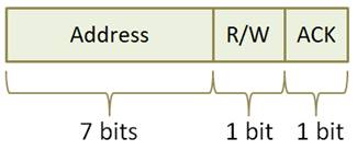
Figure 2: Showing a unique 7-bit slave address with trailing Read/Write command and Acknowledgement message.
Above we can see that the address frame is composed of a 7-bit address, followed by a read/write (R/W) bit, and finally an acknowledgement (ACK) bit. The R/W bit is set to a 1 if the master wants to read from the slave or a 0 if it wants to write. The ACK bit is pulled low by the slave as an acknowledgement to the master that it is ready to receive or send data. If the bit is set to 1, then we know the slave device has failed to respond to the request.
As an alternative, a 10-bit address may be used. This approach would be necessary in larger systems, where the quantity of unique addresses provided by 7 bits is insufficient with regard to the number of devices involved. In this case, 2 address frames are sent back-to-back. In the first frame, the first 5 bits are set to ‘11110’, followed by 2 address bits, the R/W bit, and an ACK bit. In the second address frame, the first 8 bits are used as address bits, and the last bit serves as an ACK bit, as illustrated below.
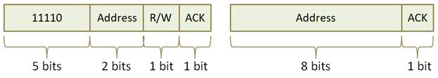
Figure 3: A 10-bit address used by master to invoke a slave response (left). A 9-bit slave response to the host (right).
Much like the school teacher in our analogy above, the master decides what to do should the slave device fail to acknowledge the address frames. Assuming, however, the slave device responds as we would expect, the data frames are the next to get put on the line. These frames are 9 bits wide, and contain 8 data bits and 1 ACK. When the receiving device has gotten all 8 bits of data, it pulls the line low to set the ACK bit to 0. An ACK bit value of 1 indicates that the receiving device did not get the message. The total picture of this master/slave communication, from address frame to data sent, is illustrated below.
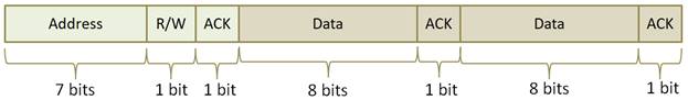
Figure 4: A complete data transmission between master and slave, from initiation to completion.
As a side note, for slave devices that have multiple internal registers, it is a common convention (though not part of the standard) for the master to specify which register to read or write. When this is the case, as in our example below, this information is sent immediately following the address frame and before the data frame. The number of these registers and their function are specific to the individual slave devices themselves, and information regarding them will be found in the data sheet for the device in question.
If at any time, the slave needs a bit more time to process the data than the master provides, the slave device can perform an operation called “clock stretching”. With this, the slave holds the SCL line low after its ACK bit, which will prevent the master from sending data until the line is released.
When all of the data frames have been sent, the master will initiate the stop condition. The stop condition is defined as the SCL line transitioning from low to high followed by the SDA transitioning from low to high. After this is completed, and if desired, the bus is free for another master to claim it and initiate a new sequence of communications.
There are times when the master may want to send several messages back-to-back without giving up control of the bus, however. It is able to do this by using the repeated start condition in place of the stop condition. To do this, the following should take place on the SDA and SCL lines, in the order given:
- The SDA line goes high while the SCL line is low
- The SCL line goes high
- The SDA line goes low while the SCL is still high
- The SCL line goes low
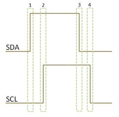
Figure 5: showing the sequence of high and low signals to establish I2C communications.
Example
What good is an explanation without an example to follow it up? Below, we go through our temperature sensor example, which illustrates how easily a NetBurner MOD5441X module can be used to talk to a temperature sensor with our I2C driver. Many of the details that we discussed above are tucked away nicely and what’s left is a clean and easy to use interface.
/******************************************************************************* * MOD5441x I2C Temp Sensor ******************************************************************************/ #include "predef.h" #include #include #include #include #include #include #include extern "C" { void UserMain(void * pd); } const char * AppName="5441x I2C Temp Sensor"; // Devine which I2C module to use on the CPU #define I2C_CHANNEL 0 // The address of our slave device, the temperature sensor #define I2C_TEMP_SENSOR_ADDRESS 0x48 /* Use I2C to read a byte from the specified register on address 0x48 */ uint8_t read8( uint8_t reg ) { uint8_t rx = 0; // This will initiate the communication to the slave, and then specify which // register on the slave we want to read from. We set the last parameter to false, // which prevents the master from sending the stop condition. int status = MultiChannel_I2CSendBuf( I2C_CHANNEL, I2C_TEMP_SENSOR_ADDRESS, ®, 1, false ); if( status != I2C_MASTER_OK ) { iprintf("Error %d calling I2CSendBuf()rn", status); } // Issue the restart, so that we can send another message immediately status = MultiChannel_I2CRestart( I2C_CHANNEL, I2C_TEMP_SENSOR_ADDRESS, I2C_START_READ ); if( ( status != I2C_OK ) | ( status != I2C_NEXT_READ_OK ) ) { iprintf("Error %d calling I2CRestart()rn", status); } // Send the next message to the sensor, which is a read request. The temperature // sensor should respond with the data in the register that we specified before. status = MultiChannel_I2CReadBuf( I2C_CHANNEL, I2C_TEMP_SENSOR_ADDRESS, &rx, 1 ); if ( ( status != I2C_OK ) && ( status != I2C_NEXT_READ_OK ) ) { iprintf("Error %d calling I2CReadBuf()rn", status ); } return rx; } void UserMain(void * pd) { //Some general housekeeping and device setup work is done here InitializeStack(); if( EthernetIP.IsNull() ) { GetDHCPAddress(); } OSChangePrio(MAIN_PRIO); EnableAutoUpdate(); uint8_t Temp; // Initialize our I2C device to the default module on the processor MultiChannel_I2CInit( I2C_CHANNEL ); iprintf("Application startedn"); while( 1 ) { OSTimeDly( 2 ); //The register 0 on this temp sensor is the given temperature in C (as dictated // by the data sheet for the sensor) Temp = read8( 0x00 ); iprintf("Temperature from sensor is %d. rn", Temp); } }
Conclusion
To wrap things up, I2C is an extremely practical choice when you need to synchronously interface one or more master devices with up to 1008 slave devices. Since it only requires two lines, your wiring and cable designs are simplified considerably. Once you get your head around the fundamentals, we hope you find it an approachable and empowering protocol. I2C is well worth considering for your next design or product — just think of the scalability, savings in materials and assembly along with reduced probability of electro-mechanical failures!
Take a look at NetBurner’s full line of Embedded Processing Modules and Web Servers that provide the I2C bus. All products include superb documentation, drivers, example code, the Eclipse IDE software, and great support!
I2C included with NetBurner:
- Embedded Ethernet Web Servers — Core Modules: https://www.netburner.com/products/core-modules
- Serial to Ethernet Servers: https://www.netburner.com/products/serial-to-ethernet