Overview
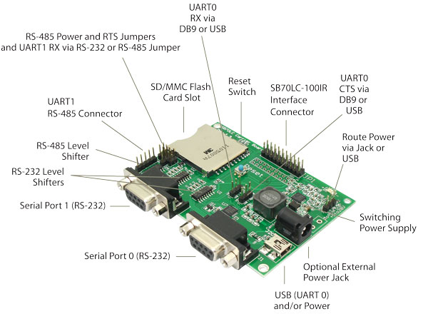
The SB70LC Development Board enables you to evaluate and develop with the SB70LC module. Peripherals are also included as example circuits that can be copied to your own design. Extension headers make it easy to connect to external hardware. The USB port can be used to monitor UART0 and/or power the board. The DB9 serial port connectors provide RS-232 serial communication for UART0 and UART1.
- Note
- The default connection for UART0 is the USB port. You must change the appropriate hardware jumpers if you wish to route UART0 through the DB9 connector.
Features
- Input power can be routed from the USB connector (default), or external power jack (5-12 VDC).
- UART0 can be routed to the USB connector (default), as RS-232 through the associated DB9 connector.
- UART1 can be routed as RS-232 through the UART1 DB9 connector (default), or as RS-485 through the J4 5-pin header connector.
- The RS-232 DB9 serial port connectors have DTE pin-outs, so a null-modem cable is not required.
Default Setup
It is recommended that you become familiar with the NetBurner tools and development environment using the factory default configuration as described below:
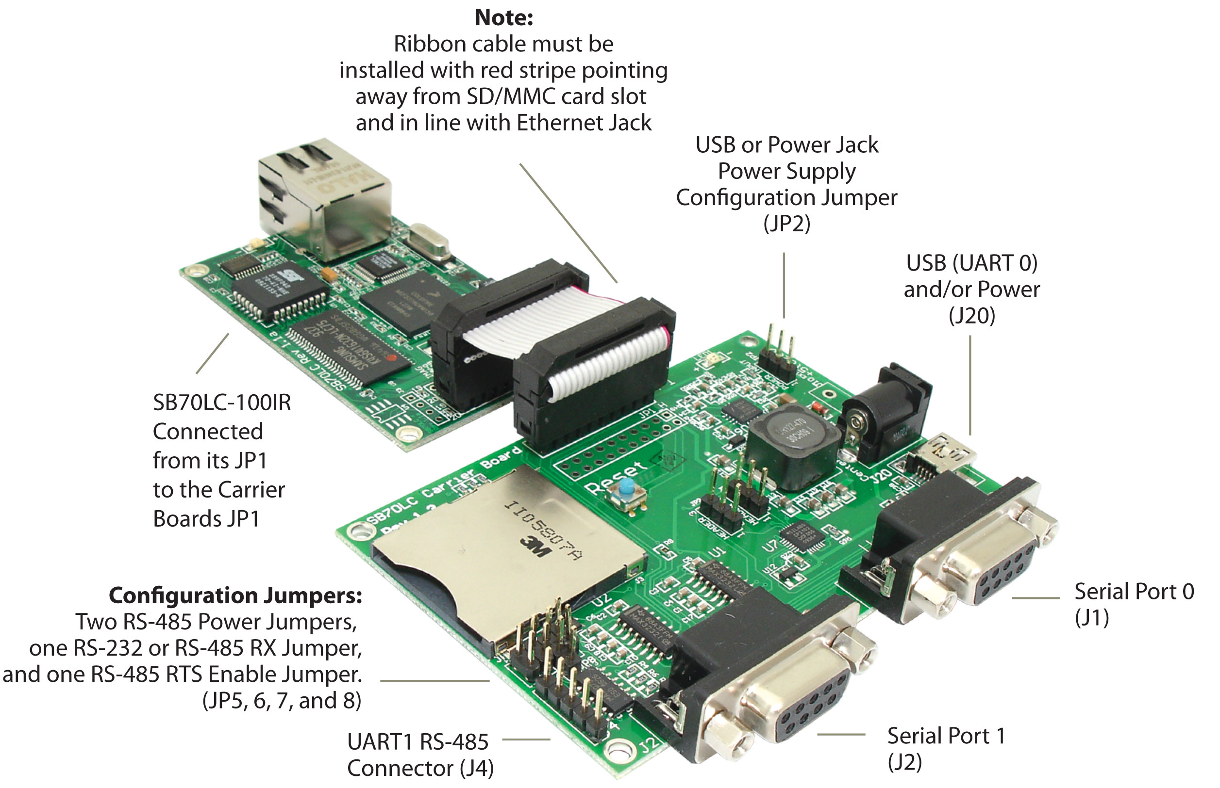
- Connect the SB70LC module to the development board JP1 2x10 header with the provided 20-pin ribbon cable.
- The default serial port configuation is UART0 through USB and UART1 throuh the UART1 DB9.
- UART0 is the default for the boot monitor interface and status messages from the application (the stdio interface), and UART1 is the data interface. All these settings and fucntions can be chagned later.
Jumper Configuration
| Jumpers | Description | Configuration |
|---|---|---|
| JP2 | Power - USB | [1 2] 3 |
| JP2 | Power - external power jack | 1 [2 3] |
| JP3 | UART0 RX - USB Connector | [1 2] 3 |
| JP3 | UART0 RX - DB9 Connector | 1 [2 3] |
| JP4 | UART0 CTS - USB Connector | [1 2] 3 |
| JP4 | UART0 CTS - DB9 Connectort | 1 [2 3] |
| JP5 | Normal Polarity - UART1 RS-485 +/- | No Jumper |
| JP5 | Reverse Polarity - UART1 RS-485 -/+ | Jumper |
| JP6 | UART1 RS-485 full duplex mode | No Jumper |
| JP6 | UART1 RS-485 half duplex mode | Jumper |
| JP7 | Route UART1 RX from DB9 connector through rs-232 (J2) | [1 2] 3 |
| JP7 | Route UART1 RX from 5 pin header through rs-285 (J4) | 1 [2 3] |
| JP8 | UART1 RS-485 echo enabled | No Jumper |
| JP8 | UART1 RS-485 echo disabled | Jumper |
Serial Port Routing
| Jumpers | Description | Configuration |
|---|---|---|
| UART0 via USB | JP3[1-2],JP4[1-2] | N/A |
| UART0 via RS-232 (J1) | JP3[2-3],JP4[2-3] | N/A |
| UART1 via RS-232 DB9 (J2) | JP7[1-2] | N/A |
| UART1 full-duplex RS-485 5-pin header (J4) | JP7[2-3] | JP6 |
| UART1 half-duplex RS-485 5-pin header (J4) | JP6[1-2],JP7[2-3] | N/A |
Hardware Signals
There are two 20-pin headers on the SB70LC module: one is populated with a 0.1-inch dual-row male header, and the other one is not populated. The unpopulated position has the same signals, and it is intended to be used for applications that may require the header on the non-component side of the board assembly.
For hardware signal information please refer to the data sheet on the product page at www.netburner.com: SB70LC Data Sheet.