Loading...
Searching...
No Matches
MOD-DEV-70 Development Board
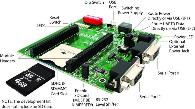
MOD-DEV-70 Carrier Board
Configure the Default Serial Port
The hardware features on the carrier board help you evaluate your peripheral connectivity and to configure the core module. DB9 connectors use the onboard RS-232 level shifter, allowing devices to connect via the serial ports. Extension headers make it easy to connect to a daughterboard or wrapping board for your specific application. The USB port can be used to monitor UART0 and/or power the board.
Most development boards include two serial ports. UART0 serial is routed to the USB port and to the DB9 connector labeled UART0. UART1 is routed only to the DB9 connector labeled UART1. The default mode for UART0 serial isthrough the USB port. To change the default mode, set the specified jumpers below to the desired position.
Serial Data Routing Options
| Development Board | Jumpers | Description | Configuration |
|---|---|---|---|
| MOD-DEV-70 | JP2,JP3 | USB | [1 2] 3 |
| JP2,JP3 | UART0 | 1 [2 3] |
ADC and DAC Peripherals
In order to successfully use the ADC and DAC peripherals, to jumpers will need to be set on the MOD-DEV-70. These connect the 3.3v and ground references that are used by the peripherals.
Power and Ground Connections for ADC and DAC Peripherals
| Development Board | Jumper | Description | Configuration |
|---|---|---|---|
| MOD-DEV-70 | JP5 | 3.3v Reference | Jumpered |
| JP6 | Ground | Jumpered |
Development Board Power
The MOD-DEV-70 development board can be powered using a standard micro USB cable (included), or an optional external power supply with a voltage between 7.5V - 12V DC. The default power jumper setting if for USB power. Set the jumper below to change the power source.
Power Supply Routing Options
| Development Board | Jumper | Description | Configuration |
|---|---|---|---|
| MOD-DEV-70 | JP1 | USB | [1 2] 3 |
| JP1 | Power Jack | 1 [2 3] |
