|
Quick Start Guides
|
|
Quick Start Guides
|
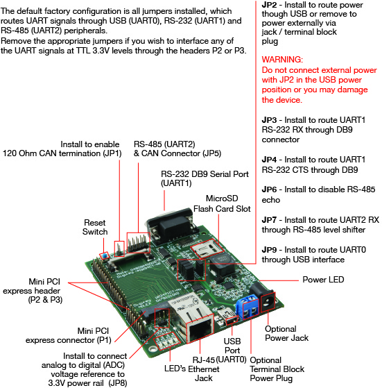
The NANO Adapter/Development board enables you to evaluate and develop with the NANO54415-200IR module. Peripherals are also included as example circuits that can be copied to your own design. Extension headers make it easy to connect to external hardware. The USB port can be used to monitor UART0 and/or power the board. The DB9 serial port connector is connected to UART1 on the processor.
The following are some features of the NANO-Dev Adapter Board:
For the most up to date pin references and schematics, visit the product page.
The default configuration is:
/note If you want to access any of these signals as 3.3V TTL on headers P2 or P3, be sure to remove the appropriate jumpers to disconnect from level converters.
| Jumper | Description | Configuration |
|---|---|---|
| JP1 | CAN 120 ohm termination resistor | Jumper |
| JP1 | No connection | No Jumper |
| JP2 | Power - USB * | Jumper 1-2 |
| JP2 | Power - External power supply (optional) | Jumper 2-3 |
| JP3 | UART1 RX - RS232 DB9 Connector * | Jumper |
| JP3 | UART1 RX - Mini PCI Express at TTL 3.3V | No Jumper |
| JP4 | UART1 CTS - RS-232 DB9 Connector * | Jumper |
| JP4 | UART1 CTS - Mini PCI Express at TTL 3.3V | No Jumper |
| JP6 | UART2 RTS - RS-485 echo enable | Jumper |
| JP6 | UART2 RTS - Mini PCI Express at TTL 3.3V | No Jumper |
| JP7 | UART2 RX - RS-485 level shifter (JP5) * | Jumper |
| JP7 | UART2 RX - Mini PCI Express at TTL 3.3V | No Jumper |
| JP9 | UART0 RX - USB * | Jumper |
| JP9 | UART0 RX - Mini PCI Express at TTL 3.3V | No Jumper |
| Mode | Jumpers Enabled | Jumpers Removed |
|---|---|---|
| UART0 via USB | JP9, JP2[1-2] | N/A |
| UART0 via Mini PCI Express | N/A | JP9 |
| UART1 via RS-232 DB9 | JP3, JP4 | N/A |
| UART1 via Mini PCI Express | N/A | JP3, JP4 |
| UART2 via RS-485 5-pin header (JP5) | JP7, JP6 (Optional) | N/A |
| Pin | Signal | Pin | Signal |
|---|---|---|---|
| 1 | No Connect | 6 | Short to 4 |
| 2 | TX | 7 | CTS |
| 3 | RX | 8 | RTS |
| 4 | Short to 6 | 9 | No Connect |
| 5 | Ground |
| Pin | RS-485 | Pin | CAN |
|---|---|---|---|
| 1 | RX- (FD) | 2 | GND |
| 3 | RX+ (FD) | 4 | GND |
| 5 | Power | 6 | CANL |
| 7 | TX+ (FD/HD) | 8 | CANH |
| 9 | TX- (FD/HD) | 10 | GND |
The default power source is 5VDC USB power. The USB connector also provides serial communication through UART0. The P5 barrel jack and 2-pin terminal block have a voltage range of 7.5VDC - 12VDC for use with an external power adapter. Be certain to adjust the input power jumper JP2 before switching power sources. The center pin of the barrel jack is positive.
The development board demonstrats how to connect the NANO54415 using a spring clip. There is also a mounting hole so you can mount the module in place. Although the spring clip is very secure, the mounting method using the mounting screw has been used in vehicles ranging from car, trucks, planes and even rockets. Please see the app note for detials: NANO Secure Mounting.